Vision Engineering – Setting the standard for 3D stereo inspection without compromising reporting for quality control
Microscopes are standard equipment in many fields, from research facilities to manufacturing, in sectors as varied as electronics, medical technology and precision engineering. Yet when it comes to inspection or micro-assembly tasks, there is no standard ‘one-size-fits-all’ microscope that is used across applications and sectors.
Often, the starting point when setting the standard for inspection systems is the choice between digital or optical.
2D digital or 3D optical stereo – a key difference between microscopes
There are two main categories when it comes to microscopes – optical stereo, invented circa 1673, with the original binocular microscope being introduced circa 1850 – and digital microscopes, which first came to market in 1986.
Optical stereo microscopes provide a 3D stereo view, delivering images with a depth and clarity that enhances the view of the sample under the microscope. Image capture options are often an afterthought and can be clunky, as they have not been smoothly integrated into the system.
By contrast, digital microscopes offer a flat 2D image with the quality of the image depending on the quality of the camera and monitor. That said, digital microscopes offer the convenience of autofocus and a larger field of view. Additionally images of the sample are simple to capture, store and share across a network.
Both optical and digital microscopes have their advantages, so why would you choose a 3D optical stereo microscope rather than opt for digital?
Visual cues – putting it in perspective
When inspecting complex micro-components perspective is critical in understanding the finer details. An optical stereo microscope delivers binocular disparity; meaning each eye will see a slightly different view of the sample. When the two perspectives combine, the operator gains added detail and therefore a more accurate understanding of the item under the microscope. The dual points of perspective not only help to determine the exact shape of the object but also help to identify any distortion, which would otherwise be missed.
Depth perception – a key principle
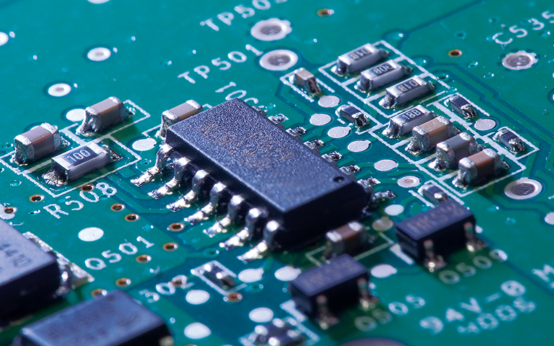
A 3D stereo view offers superior depth perception in comparison to a flat 2D image. This detailed understanding of depth is particularly important when inspection teams are assessing components with raised or recessed features, allowing operators to instantaneously distinguish the difference between a shadow and a proud or recessed feature. This is particularly helpful when it comes to components that contain multifaceted multiple parts, such as high value Printed Circuit Boards (PCBs).
Added depth perception is also invaluable when it comes to understanding complex parts. For instance in the case of the failure of a prototype part, the ability to quickly recognise a design fault may avoid a costly delay to a planned go-to-market deadline.
Understanding surface finish and texture
In instances where quality control protocols include exacting criteria for texture and surface finish an optical stereo view can make a huge difference.
Binocular disparity and depth perception are extremely useful in helping the operator spot surface irregularities straightaway. This ensures quality is maintained without slowing output.
This is something that is well understood by medical device manufacturers where smooth surfaces are critical in minimising risk to patients. An example of this is the fine finish required for artificial implants such as bone plates or hip joints. Operators will inspect these parts as soon as they have been machined, remedying any scratches or burrs by buffing and hand polishing, correcting any defects during the manufacturing process, simplifying final quality checks.
Hand-eye coordination
Hand polishing requires patience and skill, as does component assembly or re-work under the microscope. In these instances the positive impact of depth perception on hand-eye coordination should not be underestimated.
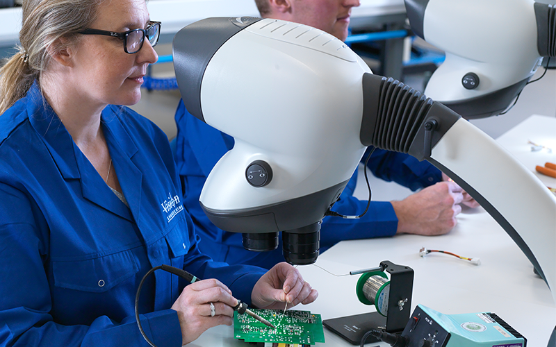
Using an eyepiece-less stereo microscope will further improve hand-eye coordination as the user sits further back from the microscope, so gaining greater peripheral vision than with a traditional binocular microscope.
Improved comfort compared to a binocular system
Improved peripheral vision is not the only benefit of the eyepiece-less microscope. The ergonomic qualities of these systems compared to binocular systems allow users to retain a natural stress-free posture for long periods, improving operator comfort, thereby maintaining accuracy and enhancing productivity.
Translating these benefits to inspection teams
Improved hand-eye co-ordination and improved operator comfort go hand in hand when it comes to improved accuracy. This is becoming ever more relevant in manufacturing as the drive towards the miniaturisation of components continues.
Take for example the production of sophisticated PCBs where surface mount technology (SMT) is part of the manufacturing process. The integrity of the component attachment to the PCB is critical to the reliable functioning of the item. To inspect these micro components and repair any faulty connections requires particular dexterity whilst working with tweezers and soldering equipment, which is markedly improved when using an eyepiece-less 3D optical system.
The delicacy of these closely packed components means that any careless movement by the operator could cause damage to the integrity of the PCB, So the ability to manipulate the 360° view of an area without needing to touch the PCB itself can be extremely useful.
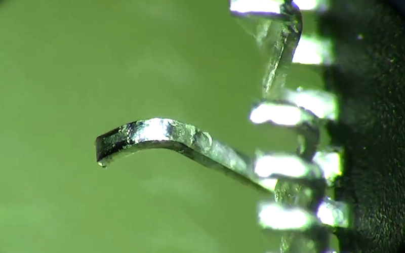
A great example of this is when the 360° rotating viewer is used with the Lynx EVO to inspect a Quad Flat Package (QFP). By using the 360° rotating viewer to look under and around the gull wings without having to manipulate the PCB itself, the risk of damage occurring during the inspection process is reduced, without impairing accuracy or speed of inspection.
The inspection of plastic components can also benefit from an optical 3D stereo view. In some cases, the colour of the component can make it difficult to identify and inspect raised areas and the superior depth perception offered by an optical microscope will make the task easier and improve operator accuracy.
Measuring the value of optical inspection
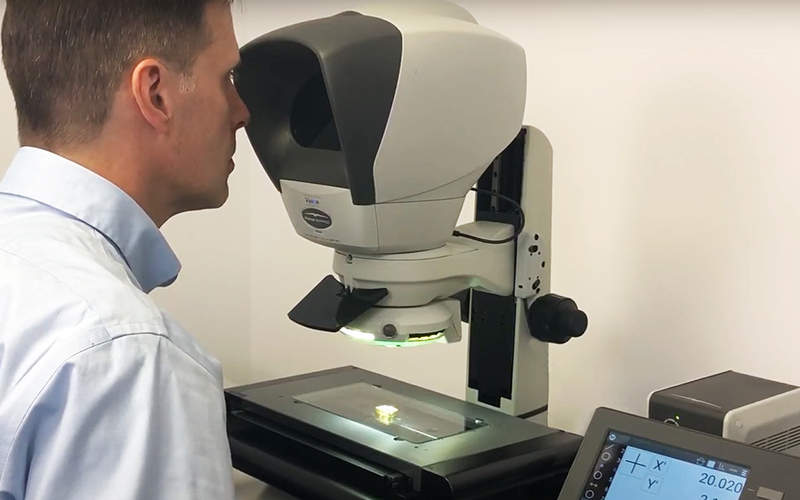
In many instances, quality control protocols call for measurement of crucial features. In numerous cases a digital system will be faster than an optical system, however an optical systems lends itself to overcoming specific challenges with certain materials, particularly where contrast is an issue.
Manufacturers of micro moulded medical parts for items such as medical plugs and drug delivery systems are very familiar with this issue. Where parts are made of transparent polymers with intricate micro geometry, the edges of critical features are far easier to detect with an optical measuring microscope. The optical head provides a crisp, higher resolution image, thereby improving edge detection and making the measurement process more accurate and efficient.
When used in shop floor applications, optical microscopes help detect edges on surface features on metal parts, where there isn’t enough contrast for video edge detection to function properly. Therefore toolmakers’ microscopes are still widely used in machine shops for quickly and accurately measuring components.
Incorporating the benefits of digital into the optical inspection process
Whilst a high quality optical image can make all the difference to understanding and assessing complex components quality control protocols will often require documentation in support of the inspection process.
In instances where simple 2D image capture is the only requirement, a digital camera can be incorporated into the optical system.
Where a greater level of detail is required a range of software options are available which can offer simple dimensioning through to extremely accurate measurements of the smallest feature, depending on the equipment used.
In instances where only a 3D image will do, out latest innovative technology provides the option of 3D digital stereo, which allows users to capture, store and share 3D digital stereo images.
Vision Engineering has the right solution for you
Vision Engineering provide a range of both optical and digital systems, as well as the systems listed below which have the option of incorporating the benefits of optical and digital systems.
Lynx EVO eyepiece-less stereo microscope
Swift PRO dual optical and video measuring system
DRV Stereo CAM 3D digital stereo microscope
For more information or to request a demo contact us
